Creating an Eclipse PDE Modeler
- Overview
- References
- Introduction
- Steps
- Create and Setup a PDE Modeler Plugin
- Defining StructuredReference Support for Domain Elements
- Defining UML Proxies for Domain Elements
- Synchronize UML Proxies with Domain Elements (The TargetSynchronizer Story)
- Synchronize Domain Elements with UML Proxies (The Mystery Behind SourceSynchronizationService)
- REW and FF
- The UI Plugin for the MMI-Based Domain Specific Modeler
- MMI UI Providers
- IMMIUIHandler
- IStructuredReferenceOpenHandler
- Drag and Drop Functionality
- Add To New/Current Diagram
- Domain Specific Palette tools
- Domain Specific Action bars
- Domain Specific UML Profiles
- FAQ
Overview
The RealTime Modeling Platform (RMP) Metamodel Integration (MMI)
framework enables a given domain model to graphically understand the
domain concepts in terms of another domain notation.
This tutorial explains how to create an Eclipse PDE Modeler. This MMI-based domain specific
modeler will visualize elements from the Eclipse PDE domain on UML diagrams. Among the many
benefits of representing domain elements as UML is the fact that the UML notation is an open
standard and is well known to the Software Development Community.
The complete code for this tutorial can be installed by running the wizard accessible from File > New > Example > RMP (RealTime Modeling Platform) > Domain Modeling Layer Plug-ins > Plug-in UML Visualization Example.
Introduction
The MMI framework provides the ability to map domain elements to
target domains such as UML, but unlike the traditional round-trip engineering based mapping,
it enjoys the following characteristics:
- Domain specific model could be partially mapped to the target domain.
- Mapping of the domain specific elements is on demand. Client controls what needs to be mapped.
- Features/properties of the target domain element are synchronized on-demand.
- Only the diagram is persisted, with views referencing domain elements.
- Target domain odels are not persisted.
The MMI framework realizes the mapping framework by allowing
MMI-based domain specific modelers to create and associate target domain proxies for
their domain elements. These proxies are synchronized on-demand, and
can be referenced without being persisted.
All class diagrams shown in this tutorials are created using the MMI-based Java Modeling
functionality, which is part of some Model RealTime modeling solutions. This tutorial
will present how to build the functionality enabling Eclipse Plugin Development Environment (PDE)
modeling. For the purpose of this tutorial, the following elements in the PDE model are considered;
IPluginBase: Interface representing a Plug-in or Fragment.
IPluginImport: Interface representing an import of a Plug-in.
The PDE Modeler will represent Plug-in as a UML Artifact, and
will represent the imports of Plug-in as client dependencies to the
corresponding artifact. At the end of this tutorial, the Eclipse
runtime will be able to support following features:
- Drag and drop a plugin.xml from Package explorer onto the diagram surface to create an artifact.
- Right click on plugin.xml in Package explorer and Visualize > Add to New Class Diagram
- Drag and drop a dependent plugin's.xml file to see the relationship between two plugins.
- Using the palette tool, create a dependency between two plugins.
- Save and open the diagram with views to Plug-ins.
- Double click on an artifact on the diagram to open the plugin.xml corresponding to it.
Steps
Create and Setup a PDE Modeler Plugin
Using Eclipse new Plugin Wizard, create a new Plugin
com.ibm.xtools.umlviz.ui.examples.pde. Don't choose any default
templates in the Wizard.
Switch to the Java Perspective.
In com.ibm.xtools.umlviz.ui.examples.pde/META-INF/MANIFEST.MF, create the following dependencies:
org.eclipse.pde
org.eclipse.pde.core
org.eclipse.pde.runtime
org.eclipse.pde.ui
org.eclipse.uml2
org.eclipse.jface
com.ibm.xtools.mmi.core
com.ibm.xtools.uml.core
Create following packages in the com.ibm.xtools.umlviz.ui.examples.pde plugin.
com.ibm.xtools.umlviz.ui.examples.pde.internal.providers
com.ibm.xtools.umlviz.ui.examples.pde.internal.handlers
Defining StructuredReference Support for Domain Elements
Not all domain models come with serializable and de-serializable referencing framework, so StructuredReference was introduced to uniformly reference all domain concepts. An MMI-based domain specific modeler must define StructuredReference for all reference-able UML proxies for their domain element. A StructuredReference representation of a domain element should have enough information to de-reference the domain element.
For more information on StructuredReference, Please refer to FAQ.
The StructuredReferences for PDE elements of interest are represented with this key information and provider ID.
| Domain Element | Key Properties | StructuredReference Provider Id |
|---|---|---|
| IPluginBase | Plugin ID, Plugin Version | pde.IPluginBase |
| IPluginImport | Client ID, Client Version, Supplier ID, Supplier Version, Supplier Match Rule | pde.IPluginImport |
To serve the structured reference for IPluginBase and IPluginImport,
- Create a class
com.ibm.xtools.umlviz.ui.examples.pde.internal.handlers.PdeStructuredReferenceHandlerextendingAbstractCachingStructuredReferenceProvider. - Open com.ibm.xtools.umlviz.ui.examples.pde/plugin.xml, and create extension to com.ibm.xtools.mmi.core.StructuredReferenceProviders.
- Create a StructuredReferenceProvider inside this extension, and set the
class to
com.ibm.xtools.umlviz.ui.examples.pde.internal.handlers.PdeStructuredReferenceHandler. - Define the StructuredReferenceProviderId and DomainElementType inside this Provider. DomainElementType corresponds to the domain element in the above table, and StructuredReferenceProviderId is the Provider ID of the domain element.
- The following is the final extension for the PDE UML StructuredReferenceHandlerProvider:
<extension
      id="pdeumlstructuredreferencehandler"
      name="StructuredReferenceHandler for PDE constructs"
      point="com.ibm.xtools.mmi.core.StructuredReferenceProviders">
   <StructuredReferenceProvider
         class="com.ibm.xtools.umlviz.ui.examples.pde.internal.handlers.PdeStructuredReferenceHandler">
      <StructuredReferenceProviderId id="pde.IPluginBase"/>
      <DomainElementType class="org.eclipse.pde.core.plugin.IPluginBase"/>
      <StructuredReferenceProviderId id="pde.IPluginImport"/>
      <DomainElementType class="org.eclipse.pde.core.plugin.IPluginImport"/>
   </StructuredReferenceProvider>
</extension>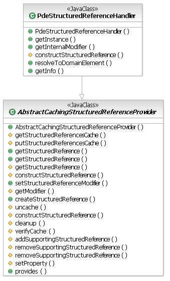
- Implement following methods inside PDEStructuredReferenceHandler:
public StructuredReference createStructuredReference(Object referencedContext, Object domainElement)
The implementation of this method should create a StructuredReference given a domain element. As per registration in plugin.xml, this handler should support creation of StructuredReferences for IPluginBase and IPluginImport.public Object resolveToDomainElement(Object referencingContext, StructuredReference sRef)
The implementation of this method should resolve the given StructuredReference to a domain element, else return null. As per registration in plugin.xml, this handler should support resolution of pde.IPluginBase and pde.IPluginImport provider ID to a proper instance of IPluginBase and IPluginImport respectively.public Object getInfo(Object referencedContext, StructuredReference sRef, String infoName)
The implementation of this method should return the value of the property for the given StructuredReference. The most commonly requested properties are defined in StructuredReferenceConstants.
Defining UML Proxies for Domain Elements
The key to represent domain concepts on UML diagrams is to map them
properly to UML. For PDE Modeler example, the mapping of domain
elements of interest to their UML counterparts is as follows:
| Domain Element | UML Counterpart |
|---|---|
| IPluginBase | Artifact |
| IPluginImport | Usage |
| IPluginBase.pluginImports | Artifact.clientDependencies |
To serve the UML proxies for the domain elements,
- Create a class
com.ibm.xtools.umlviz.ui.examples.pde.internal.providers.PdeUmlVisualizationProviderextendingAbstractModelMappingProvider. - Open
com.ibm.xtools.umlviz.ui.examples.pde/plugin.xml, and create extension tocom.ibm.xtools.mmi.core.ModelMappingProviders. - Create a ModelMappingProvider inside
this extension, and set the class to
com.ibm.xtools.umlviz.ui.examples.pde.internal.providers.PdeUmlVisualizationProvider - Set the appropriate Priority of this provider.
- Define AdaptRequest and ResolveRequest inside this provider for each domain element and StructuredReference at this priority. AdaptRequest defines what DomainElementType maps to what UML Type, and ResolveRequest defines what StructuredReference provider IDs are resolvable using this provider.
- If the domain requires different priorities for different domain elements, repeat steps 1-5 for each domain element.
- The following is the final version of
the extension for PDE UML Model Mapping Provider:
<extension
      id="pdeumlmodelmappingprovider"
      name="UML Model Mapping Provider for PDE constructs"
      point="com.ibm.xtools.mmi.core.ModelMappingProviders">
   <ModelMappingProvider class="com.ibm.xtools.umlviz.ui.examples.pde.internal.providers.PdeUmlVisualizationProvider">
      <Priority name="Medium"/>
      <AdaptRequest
            DomainElementType="org.eclipse.pde.core.plugin.IPluginBase"
            TargetKind="uml.Artifact"/>
      <AdaptRequest
            DomainElementType="org.eclipse.pde.core.plugin.IPluginImport"
            TargetKind="uml.Usage"/>
      <ResolveRequest
            TargetKind="uml.Artifact"
            StructuredReferenceProviderId="pde.IPluginBase"/>
      <ResolveRequest
            TargetKind="uml.Usage"
            StructuredReferenceProviderId="pde.IPluginImport"/>
   </ModelMappingProvider>
</extension>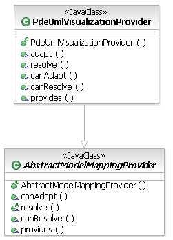
- Implement the following methods in PdeUmlVisualizationProvider:
public EObject adapt(TransactionalEditingDomain domain, Object source, EClass targetKind)
The implementation of this method should adapt a given domain Element to an EObject whose eClass is same as the targetKind specified; else return null if not supported. As per the registration in plugin.xml, PdeUmlVisualizationProvider should adapt IPluginBase to UML Artifact and IPluginImport to UML Usage.
Implementation Guidelines:
- Invoke MMIResourceCache.getCachedElement with StructuredReference of the domain element to see if the element exists in cache.
- If it isn't in the semantic cache, create a new UML element for the Domain Element.
- Activate the UML Element with the StructuredReference and the Synchronization Adapter. See Synchronize UML Proxies with domain elements.
- Invoke MMIResourceCache.cache to cache the newly created element.
public EObject resolve(TransactionalEditingDomain domain, StructuredReference sRef, EClass eClass)
The implementation of this method should resolve the StructuredReference to a proper EObject. As per registration in plugin.xml, PdeUmlVisualizationProvider should resolve<pde.IPluginBase, uml2.Artifact>to UML Artifact and<pde.IPluginImport, uml2.Usage>to UML Usage. The guidelines for implementing resolve are the same as adapt.public boolean canAdapt(TransactionalEditingDomain domain, Object source, EClass targetKind)
The implementation of this method should return true if the provider can adapt a given source element to the target kind specified.public boolean canResolve(TransactionalEditingDomain domain, StructuredReference sRef, EClass eClass)
The implementation of this method should return true if the provider can resolve the given StructuredReference to the UML proxy represented by it.public boolean provides(IOperation operation)
The implementation of this method should validate all the conditions coded in plugin.xml for this provider and any other additional conditions that must be satisfied before invoking this provider.
Synchronize UML Proxies with Domain Elements (The TargetSynchronizer Story)
The MMI framework strength lies in its ability to handle
synchronization of proxies on-demand. This means that the UML proxies
aren't synchronized unless client requests for that property.
The UML Proxies created by PdeUmlVisualizationProvider, are mere stubs
representing the domain element. The creation of these proxies involves
establishing a link between the proxy and the domain element. Also,
these proxies have to be initialized with an adapter that can populate
the properties of this UML Proxy. All this is achieved by invoking
ITarget.activate(ITargetSynchronizer, StructuredReference) on the UML
Proxy implementing ITarget. Every feature of a UML proxy can be in two
different states, Synchronized and UnSynchronized.
- A Feature of UML Proxy is in Synchronized state if the contents of the feature reflect the corresponding feature of the domain element. E.g. Attribute feature of the UML Class representing a Java Class is in Synchronized state if all the fields of java class exist as UML attributes in the UML Class.
- A Feature of UML Proxy is in Unsynchronized state if the contents of that feature do not reflect the contents of the corresponding domain specific feature.
- Every feature is initially in Unsynchronized state.
On first access,
ITargetSynchronizer.synchronizeFeatureis invoked. If synchronizeFeature returns true the feature changes its state to Synchronized. - If the feature is synchronized and the domain element is modified,
ITargetSynchronizer.synchronizeFeatureis invoked which synchronizes the feature of the UML Proxy with the domain Element properties. - If the feature is unsynchronized and the domain element is modified,
ITargetSynchronizer.verifyFeatureContentsis invoked.
- Create a stateless TargetSynchronizer implementing
ITargetSynchronizerfor every domain element. Use the singleton instance of this target synchronizer to activate the UML proxy of the domain element.
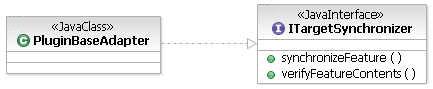
- Implement the following methods of ITargetSynchronizer:
public boolean synchronizeFeature(EObject eObj, EStructuralFeature sf, Object hint)
The implementation of this method should synchronize the contents of feature (sf) of UML proxy (eObj). If the synchronizeFeature is in response to change of domain element, then a hint may be used to optimize the process of synchronization. The implementation should return true by default, which signifies that the feature is synchronized and doesn't need any further synchronization unless marked dirty.public void verifyFeatureContents(EObject eObj, EStructuralFeature sf, Object hint)
The implementation of this method should verify the contents of feature (sf) of UML proxy (eObj). If the domain element is destroyed then the corresponding UML proxy should be destroyed from the contents of feature (sf).
Synchronize Domain Elements with UML proxies (The Mystery Behind SourceSynchronizationService)
The MMI framework provides the ability to synchronize domain
elements in response to change to UML proxies representing domain
element. The backbone of this infrastructure is the
SourceSynchronizationService. The SourceSynchronizationService
listens to changes in UML elements representing domain elements, and
invokes appropriate providers to make changes to these domain elements.
Modifications to UML Proxies aren't supported if no source synchronization provider is
found that can handle that change.
- Create a class
com.ibm.xtools.umlviz.ui.examples.pde.internal.providers.PdeUmlVizCodeProviderimplementingISourceSynchronizationProvider. - Open
com.ibm.xtools.umlviz.ui.examples.pde/plugin.xml, and create extension toom.ibm.xtools.mmi.core.CodeProviders. - Create a SourceSynchronizationProvider inside this extension, and set the class to
com.ibm.xtools.umlviz.ui.examples.pde.internal.providers.PdeUmlVizCodeProvider - Set the appropriate Priority of this provider.
- Define StructuredReferenceProviderIds of all the domain elements, whose UML proxies when changed should result in invocation of this provider.
- If the domain requires different priorities for different UML proxies, repeat steps 1-5 for each provider ID.
- The following is the final version of the extension for PDE UML Source Synchronization Provider:
<extension
      id="pdeumlsourcesynchronizationprovider"
      name="Source Synchronization Provider for UML Viz Artifacts"
      point="com.ibm.xtools.mmi.core.SourceSynchronizationProviders">
   <SourceSynchronizationProvider class="com.ibm.xtools.umlviz.ui.examples.pde.internal.providers.PdeUmlVizCodeProvider">
      <Priority name="Medium"/>
      <StructuredReferenceProviderId id="pde.IPluginBase"/>
      <StructuredReferenceProviderId id="pde.IPluginImport"/>
   </SourceSynchronizationProvider>
</extension>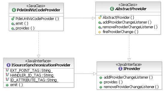
- Implement following methods in PdeUmlVizCodeProvider:
public ICommand emit(ModelChangeDelta delta)
The implementation of this method should return a Change Command capable of modifying the domain element. The changes done by this command should represent the UML Changes represented in ModelChangeDelta.
ModelChangeDelta is a composite change delta, containing all the changes that happened in the transaction.public boolean provides(IOperation operation)
The implementation of this method, should verify that the provider can provide a command for the SourceSynchronizationOperation (operation). This method should return true if the changes returned by the SourceSynchronizationOperation are handled by this provider. This method should also return true in scenarios where the command is an UnExecutable command, which signifies that the UML Changes are invalid.
REW and FF
The previous 5 sections have explained in detail, how to create a fully
functional infrastructure to visualize any given domain concepts as
UML. Also what has been explained so far is the ability to perform
two-way synchronization driven by Domain changes or UML changes.
At this time, it is recommended that some unit testing be done. Using JUnit API, the following scenarios could be tested:
- Test that the StructuredReference is correct, given a domain element.
- Test that the domain element is correct, given the StructuredReference for the domain element.
- Test that the UML Element is correct, given the domain element and the target element kind.
- Test that the StructuredReference assigned to UML Element is correct in Test c.
- Test the synchronization of a known feature of UML Element from Test c.
- Test that the UML Element synchronizes when the domain element is modified.
- Test that the domain element synchronizes when the UML Element is modified.
How good is an MMI-base modeler if the user can't visualize anything!
The following user interface features are integral parts of every MMI-based domain
specific modeler:
- Ability to drag and drop a domain element on a diagram
- Standard pop up menus on domain elements
- Add to New Diagram
- Add to Current Diagram
- Opening Editor on domain element when user double clicks on the proxy
- Palette to edit proxies representing domain elements
The rest of the document will guide you in creating user interfaces for MMI-based domain specific modeler.
The UI Plugin for the MMI-Based Domain Specific Modeler
Though not mandatory, it is a good programming practice to separate UI
from core. In addition to core dependencies, UI plugin needs to depend
on the following plugins:
com.ibm.xtools.umlviz.ui
org.eclipse.ui.ide
org.eclipse.gef
org.eclipse.gmf.runtime.common.ui
org.eclipse.gmf.runtime.diagram.ui
org.eclipse.gmf.runtime.diagram.ui.providers
org.eclipse.gmf.runtime.common.ui.services.dnd
Other must do items:
- Create
plugin.propertiesfor storing L10n strings in plugin.xml. - Create
message.propertiesfor storing L10n strings in source code.
MMI UI Providers
The MMI framework provides implementation for most commonly used
MMI-based domain specific modeler use-cases. This is made possible by creating yet another
service to manage interaction with such modelers. The
service is IMMIUIService and the providers for this service are
registered as extensions to com.ibm.xtools.mmi.ui.MMIUIProviders
extension point. The providers registered with IMMIUIService
must implement IMMIUIProvider interface.
IMMIUIProvider provides the following handlers for multiple UI components:
- IMMIUIHandler : Drag and Drop, Add to current diagram, Add to New Diagram
- IStructuredReferenceOpenHandler : To open domain editors given a StructuredReference
For our example,
- Create a package
com.ibm.xtools.umlviz.ui.examples.pde.internal.ui.providers. - Create a class
com.ibm.xtools.umlviz.ui.examples.pde.internal.ui.providers.PdeUmlVizUIProviderimplementingIMMIUIProviderand extendingAbstractProvider. - Open
com.ibm.xtools.umlviz.ui.examples.pde/plugin.xml, and create extension tocom.ibm.xtools.mmi.ui.MMIUIProviders. - Create a MMIUIProvider inside this extension, and set the class to
com.ibm.xtools.umlviz.ui.examples.pde.internal.ui.providers.PdeUmlVizUIProvider - Set the appropriate Priority of this provider.
- Register this MMIUIProvider to provide MMIUIHandler for Class, Freeform and Deployment diagram. Also register this MMIUIProvider to provide MMIUIHandler for IFile objects with name plugin.xml.
- Register this MMIUIProvider to provide OpenStructuredReferenceHandler for StructuredReference with provider ID �pde.IPluginBase�.
- The following is the final version of the extension for PDE UML MMI UI Provider:
<extension
      id="pdeumlmmiuiprovider"
      name="MMI UI Provider for PDE"
      point="com.ibm.xtools.mmi.ui.MMIUIProviders">
   <MMIUIProvider class="com.ibm.xtools.umlviz.ui.examples.pde.internal.ui.providers.PdeUmlVizUIProvider">
      <Priority name="Medium"/>
      <MMIUIHandler
            name="PdeVizUIHandler"
            uiObjectClass="org.eclipse.core.resources.IFile">

         <enablement>
            <or>
               <test property="com.ibm.xtools.mmi.ui.DiagramTypePropertyTester" value="Freeform"/>
               <test property="com.ibm.xtools.mmi.ui.DiagramTypePropertyTester" value="Class"/>
               <test property="com.ibm.xtools.mmi.ui.DiagramTypePropertyTester" value="Deployment"/>
            </or>
         </enablement>

      </MMIUIHandler>
      <OpenStructuredReferenceHandler name="PdeVizOpenHandler">
         <StructuredReferenceProviderId id="pde.IPluginBase"/>
      </OpenStructuredReferenceHandler>
   </MMIUIProvider>
</extension>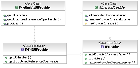
- Implement the following methods in PdeUmlVizUIProvider:
public IMMIUIHandler getUIHandler(Object uiObject, IUIContext uiContext)
The implementation of this method should return the IMMIUIHandler given a UI Object and UI Context. What differentiates a UI Object from Domain Object is that every Object on which a user action can be performed is a UI Object, but only few elements are identified by the MMI-based domain specific modeler as domain elements.public IStructuredReferenceOpenHandler getStructuredReferenceOpenHandler(String providerId)
The implementation of this method should return the IStructuredReferenceOpenHandler for the given structured reference provider ID. StructuredReferenceOpenHandler opens domain editors for given structured reference.public boolean provides(IOperation operation)
The implementation of this method should validate the operation properties to ensure that this provider can provide for the given operation. The different operations passed to a MMIUIProvider areGetUIHandlerOperation,GetStructuredReferenceOpenHandlerOperation. In the PDE Modeler example, the provides method implementation need to check the file name of the object inGetUIHandlerOperation. The allowed filenames are plugin.xml and fragment.xml. For all other operations, the provider returns true as the information specified in extension is sufficient to validate provider activation condition.
IMMIUIHandler
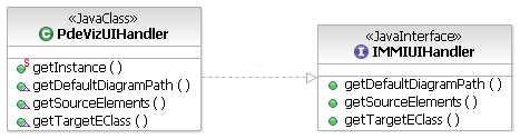
The implementation of this interface requires implementation of following methods:
public IPath getDefaultDiagramPath(Object uiObject, IUIContext uiContext)
The implementation of this method should return the location of a folder in the workspace, where the domain modeler would prefer to keep the diagrams of given uiContext.public List getSourceElements(Object referencedContext, Object uiObject, IUIContext uiContext)
The implementation of this method should return the domain elements contained or represented by the uiObject, that can be visualized on diagrams of given uiContext.public EClass getTargetEClass(Object referencedContext, Object source, IUIContext uiContext)
The implementation of this method should return the target element kind given the domain element and the uiContext. There are scenarios where the same domain object can be visualized as different UML element on different diagrams.
IStructuredReferenceOpenHandler
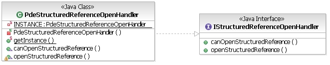
The implementation of this interface requires implementation of following methods:
public boolean canOpenStructuredReference(Object referencedContext, StructuredReference sRef)
The implementation of this method should check whether the editor can be opened for the given StructuredReference. Return true if the editor can be opened, else return false.public void openStructuredReference(Object referencedContext, StructuredReference sRef, IProgressMonitor monitor)
The implementation of this method should open the editor for the given StructuredReference. Additionally, the implementation can position the cursor in the editor to a specific item depending on the StructuredReference.
Drag and Drop Functionality
Every domain modeler provides some functionality to drag and drop
domain elements onto the diagram surface. The MMI framework provides a
Drop Target Listener to register with Drag and Drop Service. This Drop
Target Listener provides ability to drag from the custom viewer onto the
diagram surface and visualize the domain element as suggested in Domain
MMIUIProvider. Please refer to Technical_Note_DnD_Infra.
In PDE Modeler example, the ability to drag and drop from the Package Explorer onto diagram is defined as follows:
<extension
      id="pdeumldragdropProvider"
      name="Drag and drop Provider for PDE Visualization"
      point="org.eclipse.gmf.runtime.common.ui.services.dnd.dragDropListenerProviders">
   <DragDropListenerProvider
         class="com.ibm.xtools.mmi.ui.dnd.MMIDragDropTargetListener"
         id="com.ibm.xtools.umlviz.ui.examples.pde.pdedndlistenerprovider">
      <Priority name="Low"/>
      <!-- supporting drop on MMI-based domain specific modeler editor -->
      <ViewId id="UMLVisualizerEditor">
         <ElementType class="org.eclipse.gmf.runtime.diagram.ui.editparts.DiagramEditPart">
            <OperationType operation="drop">
               <TransferId transferId="JDTLocalSelectionTransfer"/>
            </OperationType>
         </ElementType>
      </ViewId>
      <!-- supporting drop on modeling editor -->
      <ViewId id="ModelerDiagramEditor">
         <ElementType class="org.eclipse.gmf.runtime.diagram.ui.editparts.DiagramEditPart">
            <OperationType operation="drop">
               <TransferId transferId="JDTLocalSelectionTransfer"/>
            </OperationType>
         </ElementType>
      </ViewId>
   </DragDropListenerProvider>
</extension>
Add To New/Current Diagram
The most used actions for domain modelers is Add To New Class
Diagram and Add to Current Diagram. The MMI framework provides
implementation for these actions in two classes
com.ibm.xtools.umlviz.ui.examples.pde.internal.actions.AddToNewClassDiagramAction
and
com.ibm.xtools.mmi.ui.actions.AddToCurrentDiagramAction.
Domain modelers can use these implementations to create pop up
menus. In PDE Modeler example, three menus are provided on
plugin.xml and fragment.xml:
<extension
      id="PDEPopupMenus"
      name="PDE Popup Menus"
      point="org.eclipse.ui.popupMenus">
   <!-- Add to Current/Create new -->
   <objectContribution
         objectClass="org.eclipse.core.resources.IFile"
         nameFilter="plugin.xml"
         id="pluginVisualizationPopup">
      <!-- Add to New Deployment diagram action -->
      <action
            label="%AddToNewDiagramFile.deployment.actionLabel"
            class="com.ibm.xtools.umlviz.ui.examples.pde.internal.actions.AddToNewDeploymentDiagramAction"
            menubarPath="com.ibm.xtools.umlviz.ui.VizMenu/addToNewDiagramFileMenu/diagramsGroup"
            id="addToNewDeploymentDiagramAction">
      </action>
      <!-- Add to New Class diagram action -->
      <action
            label="%AddToNewDiagramFile.class.actionLabel"
            class="com.ibm.xtools.umlviz.ui.examples.pde.internal.actions.AddToNewClassDiagramAction"
            menubarPath="com.ibm.xtools.umlviz.ui.VizMenu/addToNewDiagramFileMenu/diagramsGroup"
            id="addToNewClassDiagramAction">
      </action>
      <!-- Add to current diagram action -->
      <action
            label="%addToCurrentDiagramAction"
            class="com.ibm.xtools.mmi.ui.actions.AddToCurrentDiagramAction"
            menubarPath="com.ibm.xtools.umlviz.ui.VizMenu/addToGroup"
            id="addToCurrentDiagramAction">
      </action>
   </objectContribution>
</extension>
Domain Specific Palette Tools
Domain modelers need palette tools to create domain
elements. Creation of these palette tools is out of this document's
scope. For detailed reference on how to Create Palette tools, please
refer to the GMF documentation. High level steps are as follows:
- Create an extension to
com.ibm.xtools.diagram.ui.paletteProviders. Use theorg.eclipse.gmf.runtime.diagram.ui.providers.DefaultPaletteProvideras the class of the Palette Provider. - Create the contributions in the palette and assign a factory class to
it. The class used for PDE Modeler example
com.ibm.xtools.umlviz.ui.examples.pde.internal.ui.providers.PdeUmlVizPaletteFactory. - In PDE Modeler example, the following extension is added to support
palette tools for creating a Plugin Usage between two plugins:
<extension
      id="PdeUmlVizPaletteProvider"
      name="Palette Provider for Pde Uml Visualization"
      point="org.eclipse.gmf.runtime.diagram.ui.paletteProviders">
   <paletteProvider
         class="org.eclipse.gmf.runtime.diagram.ui.providers.DefaultPaletteProvider">
      <Priority
            name="Highest">
      </Priority>
      <content>
         <method
               name="hasNature(org.eclipse.pde.PluginNature)"
               value="true">
         </method>
      </content>
      <contribution
            factoryClass="com.ibm.xtools.umlviz.ui.examples.pde.internal.ui.providers.PdeUmlVizPaletteFactory">
         <!-- Root drawer for PDE Modeler -->
         <entry
               label="%PdeVizDrawer.Label"
               kind="drawer"
               description="%PdeVizDrawer.Description"
               path="/"
               id="PdeViz">
         </entry>
         <!-- Palette item to create usage -->
         <entry
               label="%PdeUsageTool.Label"
               kind="tool"
               description="%PdeUsageTool.Description"
               path="/PdeViz/"
               large_icon="icons/pde_usage_24x24.gif"
               small_icon="icons/pde_usage.gif"
               id="PdeUsageTool">
          </entry>
      </contribution>
   </paletteProvider>
</extension>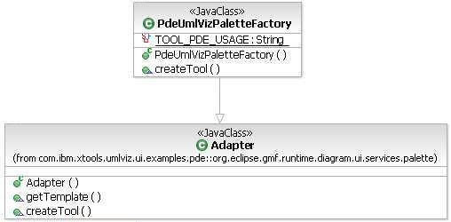
- Implement the following method in PdeUmlVizPaletteFactory:
public Tool createTool(String toolId)
The implementation of this method should create a CreationTool for a given tool ID. In the PDE Modeler example, for PdeUsageTool a ConnectorCreationTool is created. All the tools (ConnectorCreationTool, CreationTool) provided in RMP SDK, need IElementType as a parameter to the constructor. An Element type provides an Edit/Creation Command for the tool.
Domain Specific Action Bars
Domain modelers need action bars to create domain elements. Action bars are contributed by Modeling Assistant Providers. For reference on how to create and use Modeling Assistant Providers, please refer to the GMF documentation.
Domain Specific UML Profiles
At times UML proxies can not represent the entire information about the
domain element. So UML Profiles can be used to represent that extra
information. UML Profiles allow for extensibility of UML. Domain
modelers can create UML Profiles for their domains, and apply
stereotypes on UML proxies. For detailed reference on how to create and
use profiles, please refer to Tutorial on UML Profiles.
FAQ
- What is a StructuredReference?
- A StructuredReference is a structured representation of the fragment
portion of the URI. MMI-based domain specific modelers use StructuredReferences to
reference domain elements, so StructuredReferences contain information
to de-reference domain element. A StructuredReference has
following attributes:
- Provider ID: ID of the creator. This is the ID of the StructuredReferenceProvider.
- Properties: Domain element properties that are required to de-reference domain element. The properties are stored as (name, value) pairs.
- Supporting StructuredReference: StructuredReferences of other domain elements that are required to de-reference this domain element. Refactoring of this domain element is easier if supporting domain elements are represented as StructuredReferences.
- Target Kind: String representation of the target element kind.
- I can drag and drop from Package Explorer onto diagram without defining a DnD extension. Why do I have to define DnD extension when DnD is working without it?
- The reason DnD is working without defining a DnD extension is because some other plugin has defined the listener for DnD between Package Explorer and Diagram. If this plug-in is packaged with your plug-in, you don't have to define another extension for DnD.
- What is a UI Object, as referred to in IMMIUIHandler? How is it different from a domain element?
- A UI Object is any object visible in the Eclipse IDE, on which a MMI-based modeler UI operation like DnD etc can be performed. A UI Object could be a domain element or could be containing or representing many domain elements from one or more MMI-based domain modelers. Eg, an IFile UI Object can have many domain elements say IFile itself, ICompilationUnit, Java Classes inside IFile etc.
- What is the difference between synchronizeFeature and verifyFeatureContents in ITargetSynchronizer?
- Implementation of synchronizeFeature should synchronize the
contents of the feature of UML Proxy with corresponding feature of
domain element. Instead, the implementation of
verifyFeatureContents should validate whether the existing contents of
the feature of UML Proxy are valid.
E.g. To synchronize an attribute feature of UML Class representing Java Class, all the fields of Java Class should only exist as Attributes in UML Class. To verify an attribute feature of UML Class representing Java Class, validate that the existing attributes in UML Class have a valid field in Java Class.